Monicor Wireless LAN Products
|
Monicor Radio Modems
Monicor Radio Modems and Network Controllers operate under three general protocols: Point to Point Network Multidrop |
 |
What Makes |
Radio Modems
Radio modems presently available in the marketplace range over an wide variety of devices, some of which can truly be defined as radio modems while others are not. Some of these devices work well, some work marginally, and others hardly work at all. Some require special software be written for each equipment interface, some require no additional software, while the others fall in between. In portable modems, transmission ranges may vary from a few feet in some up to several miles in others. Some work well in open rooms but degrade radically when having to penetrate through one or more walls. Since the radios in radio modems can operate on frequencies bands, or use different technologies (spread spectrum), they are all subject to degradation as well as to varying degrees of interference from outside radio sources. In some cases this interference can be so great that little or no data gets through. Some units fully correct any errors caused by interference, while others do not. All of the above factors can materially affect the operating environment into which they are subjected.
Monicor's Radio modems are designed to connect to the serial interface of computers, terminals, scanners, or any other devices utilizing a standard RS-232 interface. Monicor's remote Radio Modems appear invisible to the devices to which they are connected; a terminal connected to a remote radio does not realize that it is on a radio network. For a Point to Point system and a Multidrop system, there is no requirement for the customer to change software. Monicor's Network controller provides a multiplexer/demultiplexer through the single communications port. This interface requires software support to connect the remote radio modem terminals to the various application programs.
Monicor radio modems provide two way error free data transfer. Data supplied to the transmitting Radio Modem is formed into a packet for radio transmission (X.25 format, with error detection and correction). Data received by the receiving Radio Modem is checked for errors. If data is determined to contain an error, it is retransmitted again.
Each Radio Modem has a send queue and a receive queue, each queue having space for two packets of data (packet size can vary from 16 to 128 characters user selectable). Data sent to the radio is first loaded into an edit buffer, then forwarded to the send queue once a forwarding condition has been met. Once data is in the send queue, the radio waits until it receives an interrogation from the Network Controller before sending the packet of data. Once the data is transmitted by radio, the data is retained in the send queue until the Network Controller confirms correct data has been delivered to the receive queue. If the received data had no errors, an acknowledgment is sent to the originating radio that the data was received error free at which time the next packet of data can be sent. However, if the data packet contain errors, the radio is not acknowledged and it re-transmit the data packet (as many times as necessary). This way, no data is lost.
Monicor's radio modems operate in the UHF band from 450 to 470 MHz. This band of frequencies have better propagation characteristics when used in a building environment (offices, store rooms, etc.). Generally, the higher the frequency, the more difficult to penetrate through walls (900 MHz. and 2.4 GHz., for example).
Monicor radio modems are designed for customers desiring the utmost in system reliability rather the cheapest price.
Network Controller description follows or
Return to: Top of this Page
Network Controllers
Network Controllers are similar to radio modems (description directly above) except that they form the base of the control of communication for all radio modems in a network, and require addressing to direct data to each of the different radio modems (remote terminals).
A network controller contains an edit buffer, a send and receive queue similar to a remote radio, except the network controller has an instance of these for every radio configured on the network. In addition it contains the firmware necessary to control the movement of data with all the radio modems in a network. Network controllers are generally associated with the computer that is generating the flow of data to and from the various terminals in the network. The computer tells the network controller the identification number of the radio modem followed by the data, then the network controller sends it to the proper terminal. Conversely, data from a remote radio is transferred back when the network controller interrogates that particular radio.
A single controller can communicate with up to 99 individual radio modems, determined by the configuration setting of its Link Quota. If the Link Quota is set at 1, the Network Controller and remote radio become a Point To Point operation. When the Link Quota is set greater than one, the Network Controller creates multiple send queues, receive queues and edit buffers, one for each remote radio on the network. Each remote radio uniquely identifies itself by the initial setup of its Link Number (from 1 up to 99). Data sent from a remote modem is routed to its unique receive queue in the Network Controller. Communication between the Controller and Remotes is controlled by Monicor's unique dynamic protocol that takes advantage of any "idle" terminals operating in the network to typically result in response times of less than one second.
Return to: Top of this Page
Network (Link) Operation
Link operation provides fully error corrected permanent virtual circuits, and disables multidrop operation.
PAD Interface
The PAD (Packet Assembly/Disassembly) interface provides a simple network connection for terminals or hosts using asynchronous RS-232 interfaces. The assembly is the process of grouping one or more characters of user data into a packet for error free transfer through a network.
The PAD interface is always in one of two modes: the "PAD Command Mode" or the Data Transfer Mode".
In the data transfer mode, data transmitted from a terminal or host goes to the radio and is forwarded to the corresponding remote terminal (or host).
In the command mode, terminal output is intercepted and interpreted as commands by the attached radio , and the terminal receives radio generated responses ("PAD Service Signals") instead of remote transmitted data. The terminal controls the active mode by sending certain commands.
Network Controllers and Portable Radio Modems come in a variety of case styles, power, and speeds. Click on the Model # in the tables below for individual specifications of each piece of equipment.
Remote Radio Modems
| Model # | Radio bits/sec |
Power Supply |
Enclosure |
Transmit Output Power |
| IC-15ME | 2400 or 4800 | External Source | Metal | 250mw |
| IC-20 | 2400 or 4800 | External Source | Metal | 2 watts |
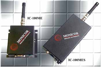
| IC-100ME | 2400 or 4800 | External source | Metal | 250mw |
| IC-100MES | 2400 or 4800 | Internal battery | Metal | 250mw |
| MT-15ME | 2400 or 4800 | External Source | Metal | 120mw |
| MS-100ME | 2400 or 4800 | External source | Metal | 120mw |
| MS-100MES | 2400 or 4800 | Internal battery | Metal | 120mw |
Network Controllers
| Model # | Radio bits/sec |
Power Supply |
Enclosure |
Transmit Output Power |
| IC-210AME | 2400 or 4800 | External Source | Metal | 250mw |
| IC-20 | 2400 or 4800 | External Source | Metal | 2 watts |
| IC-100ME | 2400 or 4800 | External Source | Metal | 250mw |
| MT-210AME | 2400 or 4800 | External Source | Metal | 120mw |
| MS-100ME | 2400 or 4800 | External Source | Metal | 120mw |
Return to: Top of this Page
Multidrop Operation
Multidrop operation uses a broadcast interface to support Terminal Equipment. When data is sent from the host (or any other remote Radio Modem), all radios will hear the data and deliver it to their respective terminal. All control of the protocol is by user software. Multidrop is useful for those protocols that operate over twisted pairs of wires with an RS-422 or RS-485 format. Under most circumstances, Monicor's system is "plug and play" with these data formats.
Multidrop operates at the speed of the radios in the Monicor equipment. When a character or characters are sent to the Radio, it is buffered in the edit buffer and radio transmission begins automatically and continues until all data has been sent. Input data to and output of data from the Monicor equipment is set to the baud rate of the terminal equipment to which they are terminated, but is transmitted over the radios at the bps rate of the radio.
Remote Radio Modems used in the Multidrop Protocol are the same as those used in Network Protocol. Click on the Model # in the tables below for individual specifications of each piece of equipment.
Multidrop operation completely overrides Link Operation, and requires the terminals and/or computers to supply the data and timing protocol. If this is not what your system needs, see the Link Operation Section.
The concept of circuits, flow control, PAD interface, packets, error correction, and most of the configuration which is associated with radios using Link Operation disappears when using Multidrop Operation.
Although multidrop operation is completely different from link operation, multidrop does use the PAD command mode interface of link operation for configuration functions.
Return to: Top of this Page
Point to Point Operation
Point to point systems perform like a hardwired link by moving RS-232 data between two devices. Point to Point is almost plug & play, simply connect a Radio Modem to Device #1 and another Radio Modem to Device #2 then send and receive data. Baud rates and Flow Control is set either in hardware or by software.
To perform Point to Point communication one type "A" Radio modem must be paired with one type "B" Radio Modem. One Modem acts as a controller and the other as a remote, however from the user point of view, they appear to be identical and can be interchanged without any effect.
Point to Point Radio Modems come in a variety of case styles, power, and speed, as delineated in the table below. Click on the Model # in the table for product specifications.
Point To Point Radio Modems
| Model # | Radio bits/sec |
Power Supply |
Enclosure |
Transmit Output Power |
| IC-15ME | 2400 or 4800 | External Source | Metal | 250mw |
| IC-20 | 2400 or 4800 | External Source | Metal | 2 watts |
| IC-100ME | 2400 or 4800 | External source | Metal | 250mw |
| IC-100MES | 2400 or 4800 | Internal battery | Metal | 250mw |
| MT-15ME | 2400 or 4800 | External Source | Metal | 120mw |
| MS-100ME | 2400 or 4800 | External source | Metal | 120mw |
| MS-100MES | 2400 or 4800 | Internal battery | Metal | 120mw |